
The figure on your screen probably will be too small to clearly see all the details. Click here to download the schematics as a full page pdf-file. Save this file on your computer, it will be often used.
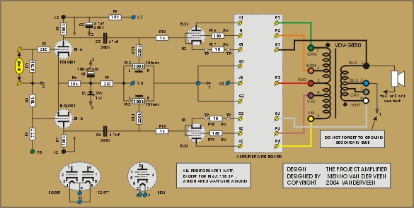
The circuit diagram contains three sections: the tube section, the amplifier wire board and the output transformer. The blue colored connections V0, V1, Vn and ground-1 plus the filament f-f refer to the power supply, as discussed in part 5.
Tube section: the tube B1 at the input is a differential amplifier and phase splitter at the same time. The cathode resistor R6 in combination with the Zener diode Dz functions as a current source ( I = 39 V / 15 k = 2.6 mA; each B1 triode gets 1.3 mA). The anode resistor R7 is a little larger than R5 to let B1-a and B1-b amplify equally. Pay notice to the bottom side of R7 which is connected to the upper side of R5 ( = V2). The capacitors C3 and C4 bring the amplified and phase inverted signals to the power tubes. Mount C4 in such a way that it can be easy disconnected, because the amplifiers 1 to 9 in the twenty amplifiers figure of part 3 do not need C4. The control grids of B2 and B3 get an adjustable (P12 and P13) negative voltage through R11 and R14 in order to trim the quiescent currents through the power tubes. Use 10 turns trim pots for easy adjustment. Mount P12 and P13 in such a way that when turned fully counter clockwise the control grids are at a maximum negative voltage. The quiescent currents can be measured over R17 and R18 with a DC voltmeter, see the Test Point connections which are 4 mm panel sockets in my amplifier. When for instance the meter reads 0.50 V over R17, the quiescent current through B2 equals 50 mA. There are two grounding points. Place ground-1 close to B2,3 and ground-2 close to B1 for minimum hum and hiss.
Wire board: The wires on this board will be routed differently for every amplifier, this will be discussed in detail later.
VDV-GIT80: The primary winding is connected directly to right side of the amplifier wire board. The wires of the secondary winding should first go to 4 mm shrouded panel sockets for speaker connection. Use extra wires to connect the secondary also to the amplifier wire board. Please don’t forget to connect the secondary blue wire (2) to ground-1.
More news to follow soon!