
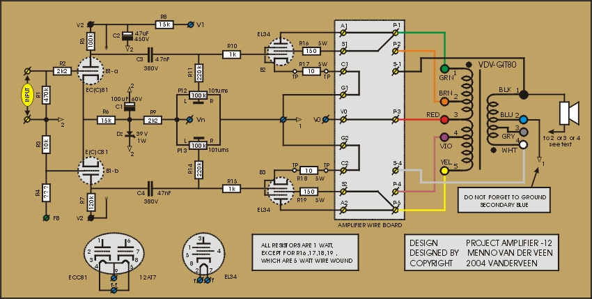
Inside amplifier 12 the screen grids are connected directly to their anodes. They behave as one and therefore this is called triode behavior. This is not totally true, because between the anode and screen grid we find grid G3 (pin-1) which is still connected to the cathode. To make each power tube a real triode we should connect pin 1 and 3 and 4 together. However, this very interesting experiment is not discussed here. Amplifier 12 has extra local feedback compared to the previous discussed amplifiers 10 and 11. See the schematics below; the technical details are found in form-12.doc (click ![]() here to download). Click the circuit diagram for full page view.
here to download). Click the circuit diagram for full page view.
The sound of amplifier12 differs much from amplifiers 10 and 11. All details are extremely clear, the spatial resolution is large, resulting in a wide and deep and detailed sound stage. Distortion is absent while there is no coloration due to the larger damping factor.
However, the measurements show that the output power has dropped from 28 to14 Watts. This loss in power is caused by the change in current-voltage characteristics of the power tubes B2 and B3. The lines have moved to the right side, like in a real triode. The lowest frequency at P-max has dropped to 10 Hz. This is logical, because 14 Watt at 10 Hz creates the same flux density in the same OPT as 28 Watt at 14 Hz. The lowest –3dB frequency is unchanged because C3 and C4 stayed the same. The highest –3dB frequency drops a little; this will be discussed later. When we compare amplifier 10 with amplifier 12, we again clearly see the influence of local feedback. The open loop amplification factor in the power tubes changes from 190 to 11.5; this is a factor of 190 / 11.5 = 16.5. We then can expect that the output impedance changes with the same factor, going from 53 Ohm to 53 / 16.5 = 3.2 Ohm. However, I measured 3.4 Ohm and this tiny little difference is caused by the wire resistances Rip and Ris of the output transformer, which I did not yet take into account. These calculations explain as well the very clean undistorted character of amplifier 12. The harmonic distortion in the power tubes has been lowered by the same factor of 16.5, which really is substantial and noticeable. Another important factor is that the primary winding of the OPT is driven now by the lower plate resistances of the power tubes. Once more this lowers the harmonic distortion inside the OPT.
There are many reasons why we can consider amplifier 12 to be a real high end amplifier. The distortion is low, the damping factor is high enough to prevent coloration with the frequency dependant impedance of the loudspeaker, we only apply very local feedback, there is no overall negative feedback between the input and output, the amplifier is almost complete in class A which delivers a stable constant load to the power supply, the output impedance does hardly change with the output power, thus minimizing Dynamic Damping Factor Distortion (= DDFD), and so on.
Next time: amplifier 13