
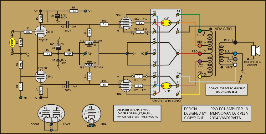
The power tubes in amplifier 18 are in pentode mode by means of a very smart circuit; now they can deliver their full output power. Two floating high voltage supplies Vht1 and Vht2 deliver the energy to this interesting amplifier. Each power tube is part of its own closed current circle including the primary winding between taps P-2 and P-4. The driver stage around B1 has not enough headroom to get the full output power, but an example is given later how to solve this. Click ![]() here to download the specifications of this special amplifier.
here to download the specifications of this special amplifier.
The sound character of amplifier18 is clean and open and detailed. The bass reproduction is powerful and controlled. This amplifier has the largest damping factor of all amplifiers in this project (and the smallest amplification factor). The -3dB frequency range is very wide because the cathodes drive the primary with their small output impedance. Also the Miller capacitance plays no role because the screen grids are at a constant voltage with respect to their cathodes and control grids.
Lets take a closer look to the upper power tube B2. Between cathode and screen grid we find a constant high voltage Vht1. This causes the power tube to behave as a pentode. The cathode drives the upper tap P-2 of the primary. The anode of B2 is connected to Vht2 and from there to the lower tap P-4 of the primary. This closes the current circle of B2. So, Vht2 is in fact the power supply for the upper tube. By means of the same reasoning it can be shown that Vht1 is the power supply for the lower power tube B3.
The driver section B1 needs a reference voltage and this is created by grounding the center tap P-3 of the primary. The high voltage supply voltage V1 for the driver section is created by means of two resistors of 10 kOhm (1 Watt) connected to Vht1 and Vht2. Both of these supplies are floating with the musical signal. However, they float in opposite direction. The summing by means of the two 10 kOhm resistors in fact distracts the audio signals from Vht1 and Vht2 and creates a constant V1.
Amplifier 17 suffered under too little drive signal from the driver stage. The same is the case in amplifier 18. I therefore now give an example of how to apply bootstrapping in a smart way to solve this. Click here to download a publication from the magazine Funkschau 24/87. I do not know the name of the inventor of this circuit, but he really is very smart and I once hope to hear his name. Also pay attention to his OPT which is an auto transformer (only one winding with smart taps). His driver stage solution is a complete solution. However, the present circuit with B1 offers the full possibility to completely evaluate the goodies of this special PPP-circuit.
Next time: brute audio power with amplifier 19