
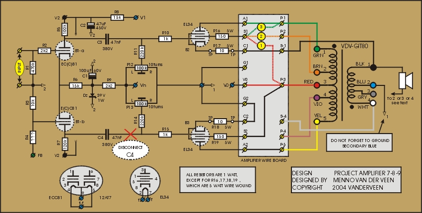
In these amplifiers the quiescent current is compensated by B3 in the primary winding of the output transformer. Also cathode feedback is applied by connecting the cathode of B2 to a tap on the secondary winding. This CFB changes the specs drastically, as I will discuss following. See the schematics for all the details and click ![]() here to download the specifications.
here to download the specifications.
Compared to amplifiers 4-5-6 we have much more output power available. It must be the CFB that causes this, because everything else has stayed the same. This extra feedback at B2 lowers its plate resistance, while nothing has changed with the large plate resistance of B3. So, in comparison to B2, the load of B3 to the primary is negligible and B3 eats almost no output power. This even can be improved by adding a cathode resistor to B3, as discussed the previous time.
It is clear that B2 and B3 have unequal plate resistances and therefore the suppression of the ripple voltage of the high voltage supply is not optimal. As said the previous time, this can be improved by adding a choke and buffer capacitor.
The optimal primary impedance for these amplifiers lays around 4 kOhm (8 Ohm speaker between secondary pins 1 and 2). I did not test this and leave it to the DIY-r to optimize these circuits.
Looking at the specs the influence of the CFB is very clear. The amplification and output impedance are much smaller now. This also means that the harmonic distortion will we reduced largely. These amplifiers are very linear and the result is a clear and very detailed soundstage.
When driving these amps to maximum output power, to clipping, they sound harsh. The local feedback tries to maintain the amps in their linear region, but at clipping there is no space available anymore for any correction. The result is a hard clipping in overdrive, and this is clearly noticeable in loud transients.
In my opinion the local feedback is a little too much; we have reached the edge, a little less would be better. Then the sound character would be more friendly and warm. So, we should change the amount of local cathode feedback. Remove the grounding at secondary pin 2 and replace this grounding to pin 4. The cathode of B2 should be connected to secondary pin 3. Now we use less secondary windings and have consequently less cathode feedback. Try it, and you will hear the improvement.
Next time: THE MATRIX