
![]() CLICK HERE TO DOWNLOAD the complete application manual (pdf).
CLICK HERE TO DOWNLOAD the complete application manual (pdf).
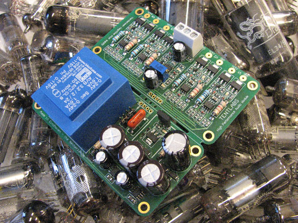
Tentlabs is known by its many practical modules for DIY construction of CD players and valve amplifiers. Together with Ir. bureau Vanderveen a new and advanced module for automatic bias control for valve amplifiers is introduced
Power valves in valve amplifiers need a good controlled and stable quiescent current for optimal operation. There are two standard methods to do so: trimming the negative control grid voltage or the use of a heavy cathode resistor. Both methods have the disadvantage of drifting of the quiescent currents through valve aging and or variation in supply voltages. Traditional servo circuits might solve this. However, they can not cope with the raising of the cathode currents at higher output levels. There the traditional circuit changes the quiescent current, which should not be the case.
In the new circuit of Tentlabs and Vanderveen, the quiescent currents are absolutely constant under aging and changes in supply voltages and power levels. The condition of operation is not of any influence anymore, like class A, AB, B or single ended or push pull. The circuit uses the amplified music itself to permanently measure only in a very small window around the selected quiescent current. Any current variations outside this window are neglected. Therefore changes of power levels and supply voltages have no influence anymore.
The new module has its own integrated power supply including negative control grid voltages and four sections to measure and regulate four power valves. It can deliver negative control grid voltages up to -160 V, while the quiescent currents can be set with only one trim pot between 0 to 175 mA.
When the valve amplifier is switched to operation, the module detects the presence of the high supply voltage. The module waits 45 seconds and then starts to raise the negative control grid voltages. This procedure creates a very soft and mild start up of the power valves, making their life span longer.
We guarantee the modules for 5 years; they are completely assembled and tested. The introduction price up till February 15 2008 equals € 149,- tax inclusive, shipment exclusive. After the introduction period the price is € 179,-. Order at www.tentlabs.com or go to 'order' on this site.
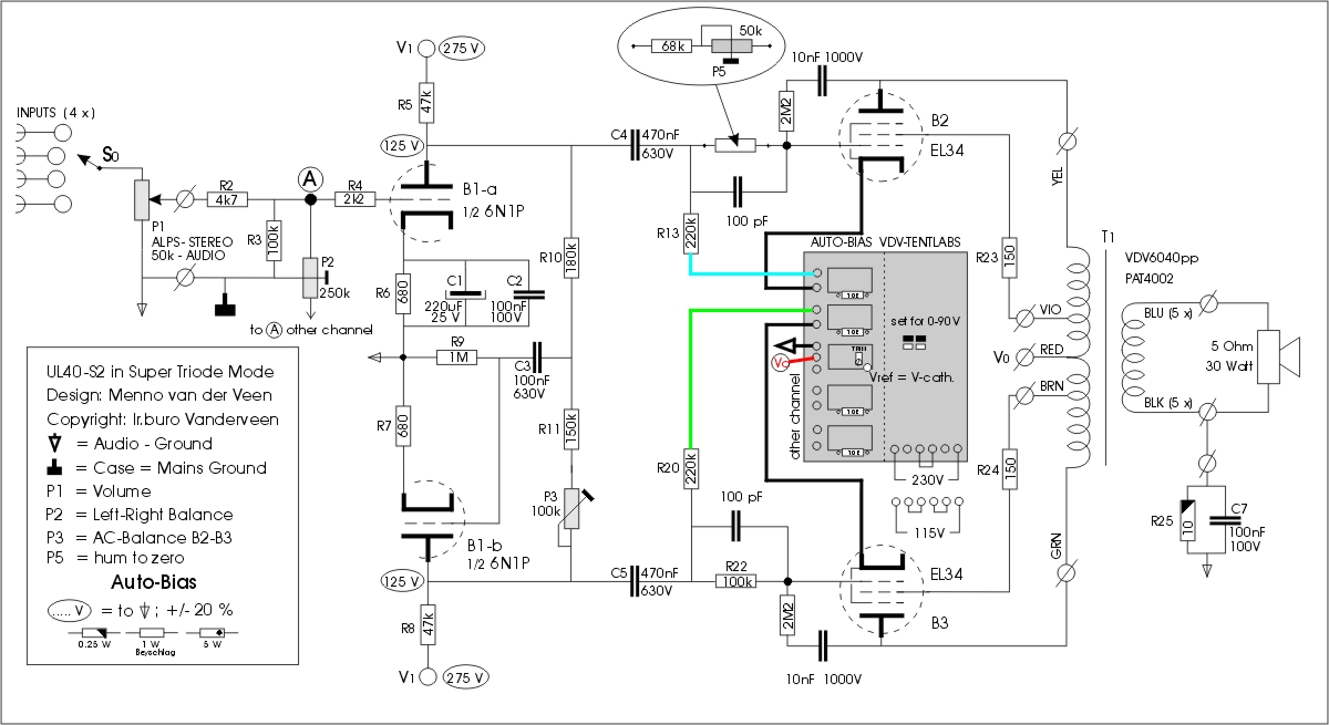
How to implement the Auto-Bias module into the UL40-S2
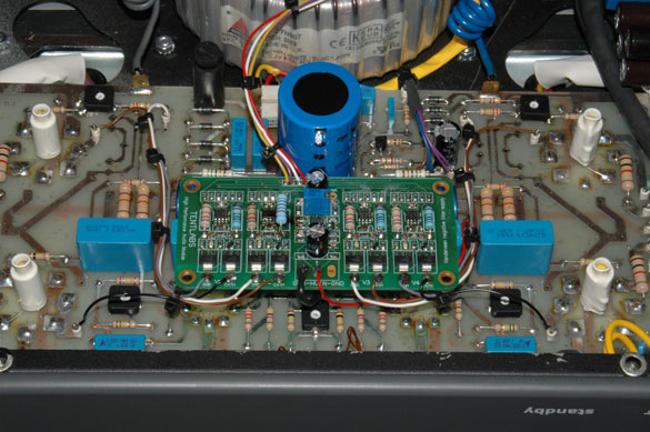
The schematics show how the Tentlabs-Vanderveen module fits into the UL40-S2 DIY kit.
First remove R14,15,16,17,18,19,21 and P4 and C6. Their function is replaced by the auto bias circuit, which can be glued on top of C4,5.
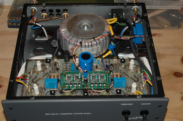
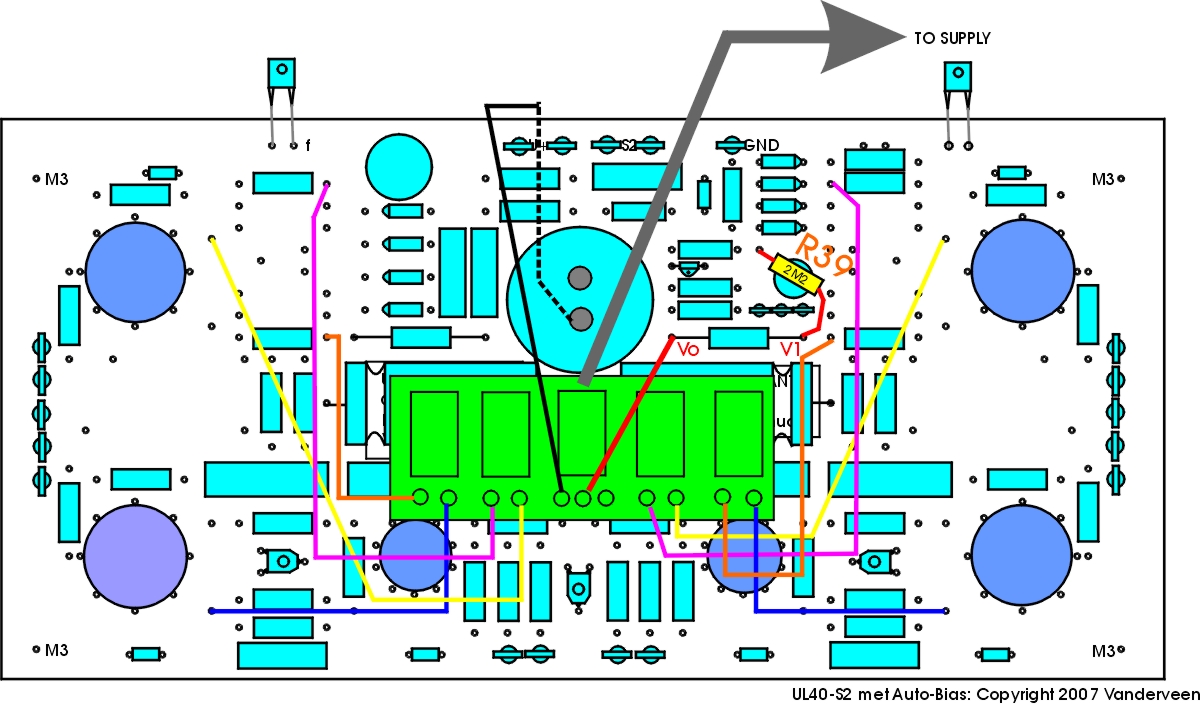
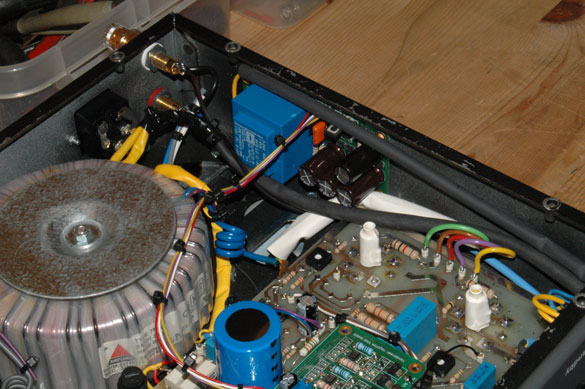
Only some new wires need to be soldered, as shown in the next figure. The supply unit is separated from the control section and placed inside the case close to the power transformer. The 230 V supply voltage can be taken from the power switch. The control unit needs the central grounding point under the main 330 uF capacitor, as well as the high voltage itself.
The module contains one trimming pot. This trimming pot is factory set for a quiescent current of 40 mA. However, per application you might need more or less quiescent current. Use a DC voltmeter (set at 2 V range) and connect it over one of the blue-gray 10 Ohm power resistors of the control section of the module. Switch on the power and stand by switches. Wait for 45 seconds and slowly the current through the selected 10 Ohm resistor will increase. Now slowly clock wise turn the trimming pot until 650 mV is measured. Each of the power valves is now exactly at 65 mA quiescent current, which is an ideal current for the UL40-S2. For any other value of the quiescent current, the same procedure can be followed.
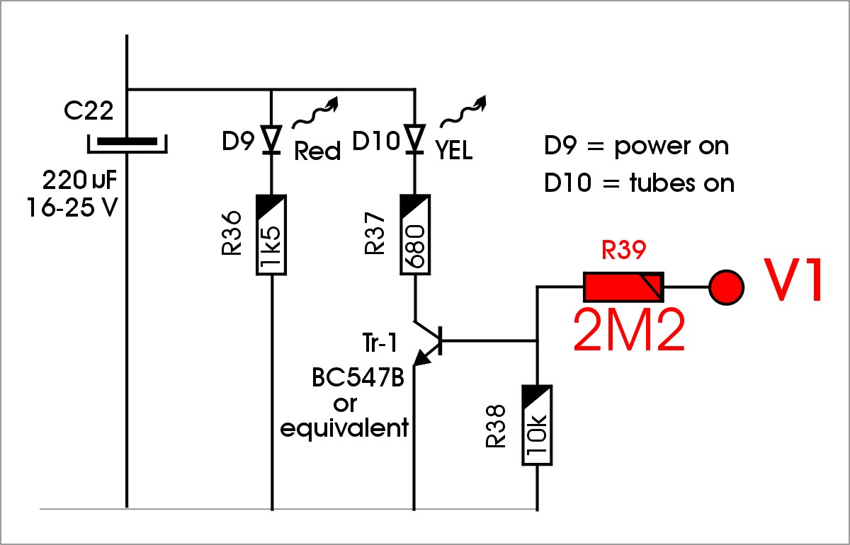
The LED-indicator above the stand by switch needs rewiring, because there is no cathode resistor present anymore. A new R39 = 2M2 is added, connected to the supply voltage V1.
What is the gain of implementing auto bias into the good UL40-S2? There is absolutely no hum anymore. The bass reproduction is largely improved because any DC magnetization inside the core of the output transformer is absent. The life span of the valves is longer and you don't need to check the valves anymore for equal quiescent currents.