
PLEASE READ THIS: Last year experience with the JJ-ECC99 has shown us two major problems that might occur. Firstly, the newest production of the JJ-ECC99 differs because more filament current is drawn, almost 20 % more than earlier versions. This all creates too much heat inside the MCML05 case, which might cause real damage to the high voltage electrolytic capacitors. They will die too early. Also the stabilization transistor BDV67B will get too hot and might blow. Secondly, we experienced excessive noise production inside the ECC99 after say half a year of use. This can’t be cured; replacement of the tube is the only solution.
Because of these two effects, I advise to read and apply the ECC99 MOD’s in a different manner: Please do NOT replace the ECC82 by the ECC99. Stay using the ECC82 with cathode resistors of 470 Ohm. Apply the circuit of MOD-2B with the ECC82. Then the sound character and specifications of this new ECC82-application will closely match the ECC99-circuit, while noise and heat are no problems anymore.
Click here to download the free modification manual
MCM-MOD-2:
SECOND MODIFICATION OF THE LINE STAGE WITH ECC99 OF THE VANDERVEEN MCML05 PRE-AMPLIFIER
These modifications are for free, you have to buy nothing. All components that you need are there. The only condition is the implementation of the first modification in my MCML05 pre-amp where the ECC82 tube is replaced by the heavier ECC99 double triode. See my site for more info about this first modification.
What follows is caused by being inspired by colleagues who did excellent research. I mention Peter Dieleman1 and Burkhard Vogel2,3. They both did deep going research on triode amplification stages, especially about the SRPP circuit (shunt regulated push-pull) and published about it in their books, which are listed below.
1) Peter Dieleman: "Buizenversterker Schakelingen"; Elektor, ISBN 978-90-5381-243-3
2) Burkhard Vogel: "How to Gain Gain"; Springer, ISBN 978-3-540-69502-8
3) Burkhard Vogel: "The Sound of Silence"; Springer, ISBN 978-3-540-76883-8
Thanks to these books and many articles on the internet plus private discussions with colleagues at the European Triode Festival 2009, I got more understanding of these peculiar triode circuits. I decided to use this new knowledge and to apply it to my own design, where I invented a strange modified SRPP circuit (which sounds extremely musical, I designed it mostly by ear).
A fresh look to MCM-MOD-1
The figure 1 below shows the schematics of the line stage of the MCML05 pre-amp with the ECC99 double triode. The signal input is at the lower control grid, while the output is connected to the lower anode. This anode is not fed by an anode resistor but by a strange current source, which is totally equal to the lower amplifying triode stage. This circuit as a total eliminates influences of changing "mu" (amplification factor) and internal resistances "ri" of the tubes while both valves together cancel out these variations. The circuit is totally symmetrical.
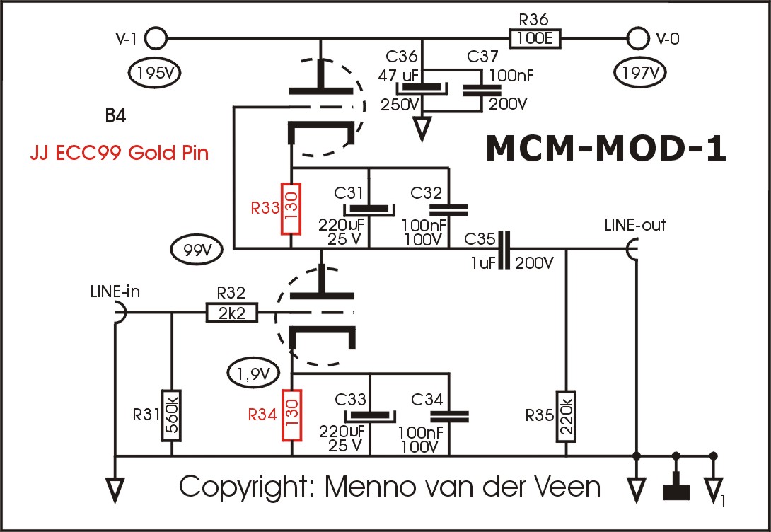
Figure 1: MCML05 MOD-1 with the ECC99
Both triode sections have a rather low impedance, with low internal noise (see 3). The effective output impedance Z-out is close to 1 kOhm. Both THD and IMD distortion figures are low. The table below shows the measurement results.
| A-0 | A-10k | Z-out | V-max | f-3H | noise | THD | IMD |
| 6,5 | 5,9 | 1,1 kOhm | 21 dBV | 70 kHz | -86,3 dBV | 0,23 % | 0,17 % |
Because these measurements will be repeated at each following modification, I now shortly explain the conditions of these measurements.
A-0: open loop amplification factor including the volume and balance potentiometers (volume at maximum and balance in mid position); the output of the pre-amp is loaded with the 1 MOhm input impedance of the oscilloscope.
A-10k: the output of the pre-amp is loaded by a 10 kOhm resistor, emulating the general input impedance of a transistor power amplifier. Tube amps have easier higher input impedances ranging from 50 to 100 kOhm. So, 10 kOhm load can be considered as the most unfavorable load for a valve pre-amp.
Z-out: this is the effective output impedance of the line stage, measured with the so called "on-off" method, where the decrement of the output voltage is measured by temporally loading the output with a 1 kOhm resistor.
V-max: maximal effective output voltage in a 10 kOhm load, expressed in dBV (0 dBV = 1 Vrms), while both THD and IMD are smaller than 1%.
f-3H: minus 3 dB frequency in regard to 1 kHz, at 0 dBV into 10 kOhm load
Noise: measured in a bandwidth of 22 kHz (44.1 kHz sampling) with a FFT size of 65536, ensuring that each Herz has a Bin (a measurement box for each Herz).
THD: Total harmonic Distortion of a 1 kHz sinus, the 0 dBV output is loaded with 10 kOhm.
IMD: Intermodulation Distortion of equal 18,5 + 19,5 kHz sine signals, the output is loaded with 10 kOhm at a summed 0 dBV signal level (-3,3 dBV per sine signal).
All these measurement figures and results tell us a lot, but it is not always easy to explain their relation to what we hear. Only numbers is not enough, we need to add subjective impressions to make the total picture clear. In other words: objective and subjective are both needed for.
The circuit of figure 1 sounds beautiful and musical, I had no complaints and enjoyed listening. But one day recently my colleague Hans van Maanen (Temporal Coherence) paid me a visit with his new all transistor pre-amplifier. Comparing mine and his made me tremble. There was much more space and details in his pre-amp. This listening session brought me to restudy my design and to find out if any improvement would be possible. The next modifications show my progress.
MCM-MOD-2A: DE AIKIDO GAIN STAGE
Figure 2 shows the simplified schematics of this new circuit. Burkhard Vogel birth names this circuit the "Aikido Gain Stage", see his book 2), chapter 9. In my line stage, on the PCB, you only have to remove the capacitors C31 and C32. See figure 3 for more information. There C31 en C32 are now white colored, meaning that they should be removed and replaced by nothing.
The higher thought behind this circuit is that the upper triode now behaves as an undampened high impedance current source. The static loadline is therefore almost horizontal, creating low distortion. The slope of the dynamic loadline equals the input impedance of the connected power amplifier, and is therefore as horizontal as possible. In this case I used a 10 kOhm load which should be considered as the most difficult load. In spite of that, the line stage functions very good, as shown in the measurement results listed below.
| A-0 | A-10k | Z-out | V-max | f-3H | noise | THD | IMD |
| 8 | 7 | 1,4 kOhm | 23 dBV | 62 kHz | -86,8 dBV | 0,11 % | 0,084 % |
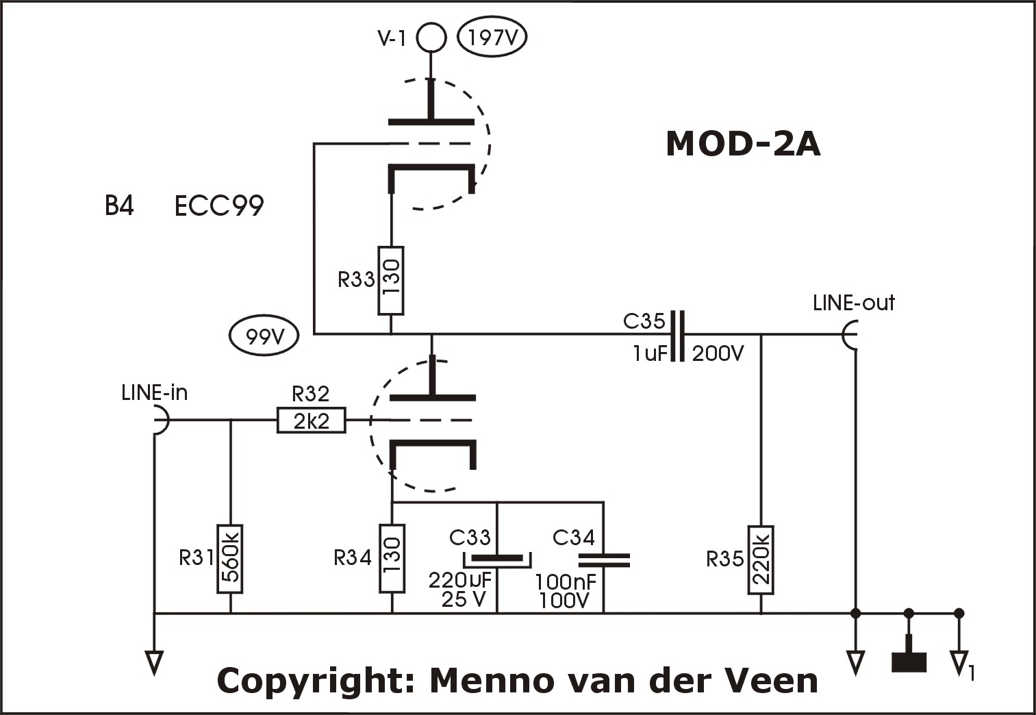
figure-2: MOD-2A Aikido Gain Stage modification
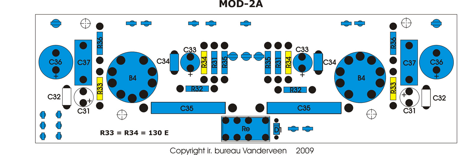
ffigure-3: MOD-2A, remove the capacitors C31 and C32
This modification works fine. The distortions are reduced by a factor of two which is a clear improvement. There is a little concern in regard to f-3H which has lowered a little, but still good enough. The cause of that is the high impedance current source which is more sensitive to stray and Miller capacities. But ....... I can improve more.
MCM-MOD-2B: Modified AIK
The distortions in MOD-2A are mainly caused by a-linearity in the lower triode. This situation can be improved by removing the capacitors in parallel with the lower cathode resistor R34. Then internal feedback in the lower triode will linearise this circuit. The only disadvantage is that the output impedance will get larger, Z-out = (ri + (mu + 1)×Rk). The figures 4 and 5 show how to implement this modification, and the table gives the measurement results.
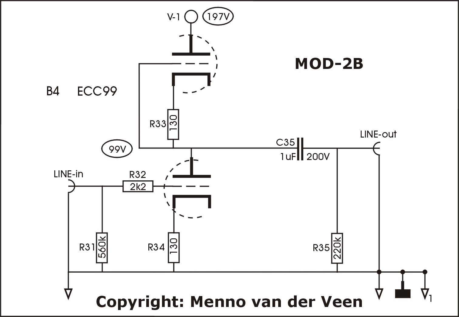
figure 4: MOD-2B, Aikido mod improved
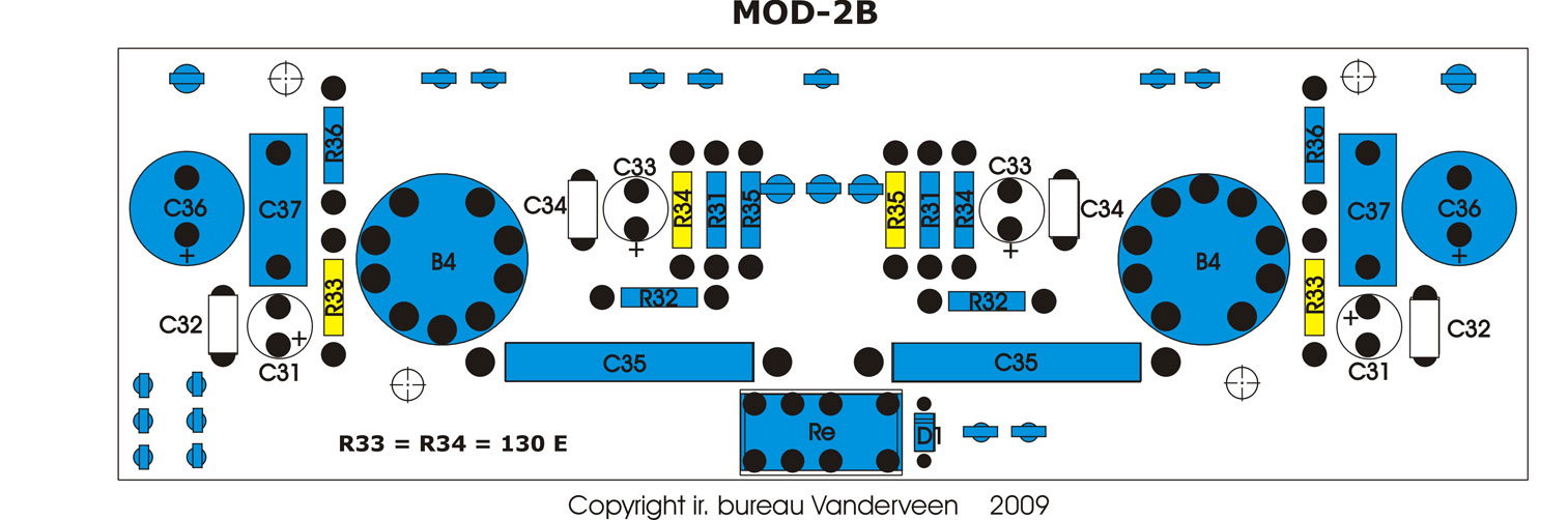
figure 5: MOD-2B, remove C31,32,33,34
| A-0 | A-10k | Z-out | V-max | f-3H | noise | THD | IMD |
| 5,7 | 4,4 | 2,5 kOhm | 23 dBV | 67 kHz | -86,8 dBV | 0,062 % | 0,046 % |
The results are in good agreement with the expectations, the distortion has again got less by a factor of two and the output impedance has raised by a factor of two.
I listened a lot to this circuit topology. I noticed that the reduce of distortion is clearly noticeable, more details in a very open and deep soundstage, soft tonal character with more than enough high being nowhere irritating. This circuit is an excellent candidate, but I still am a little worried about the higher output impedance. Therefore the next step: MOD-2C.
MCM-MOD-2C: SRPP
The next modification is the pure SRPP circuit. The output is now taken at the upper low impedance cathode. Peter Dieleman1 and Pierre Touzelet carefully calculated the optimal resistance of the upper cathode. They found: R33 = R34 × (mu+1)/(mu-1). In the here used quiescent point of the ECC99 the mu equals 22, so, R33 should get a resistance of 142 Ohm (use 120 + 22 Ohm in series). The only change, asides of the value of R33, is to change one connection of the output capacitor, as indicated with RED in figure 7.
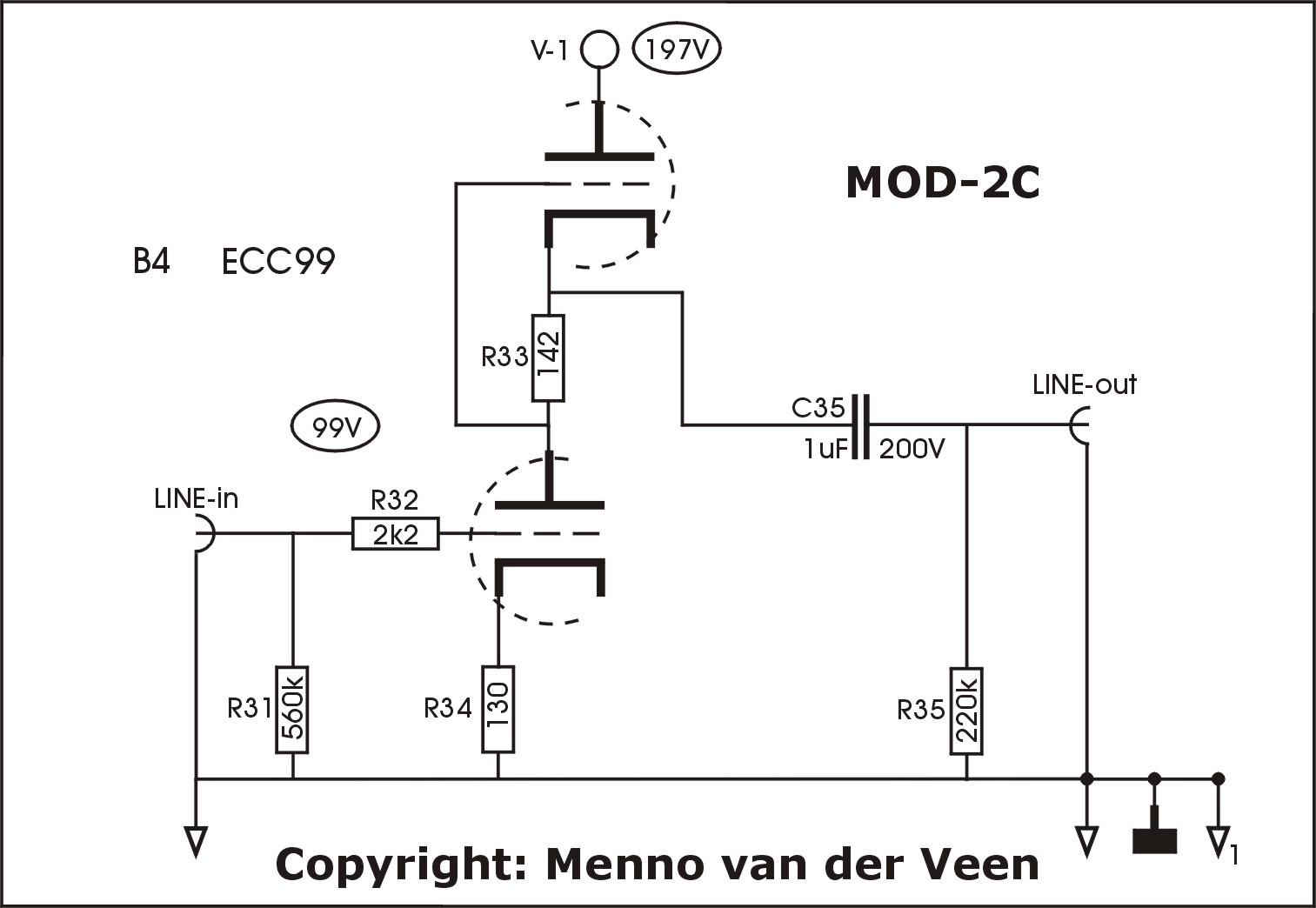
figure 6: MOD-2C, SRPP with the ECC99
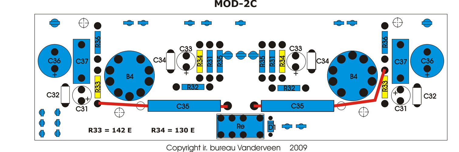
figure 7: MOD-2C, one side of C35 should be reconnected, indicated with RED.
| A-0 | A-10k | Z-out | V-max | f-3H | noise | THD | IMD |
| 5,6 | 5,0 | 1,1 kOhm | 25 dBV | 70 kHz | -86,9 dBV | 0,053 % | 0,038 % |
Again the distortions have got less and as predicted, the output impedance is smaller. Noise floor and f-3H have not changed that much, while the maximum output signal level has raised.
Listening to these last modification shows all the goodies of MOD-2B but the high tonal character has changed. You do not hear more distortions, in that regard the tonal character is soft, but you notice the high tones as being more present, more accentuated. I think (am not sure) that the lower output impedance gives another interaction with the interlinks cable used, which might cause this effect.
Compare and Conclude
The table below summarizes all the measurement results of the different modifications.
| MOD | A-0 | A-10k | Z-out | V-max | f-3H | noise | THD | IMD |
| MOD-1 | 6,5 | 5,9 | 1,1 kOhm | 21 dBV | 70 kHz | -86,3 dBV | 0,23 % | 0,17 % |
| MOD-2A | 8 | 7 | 1,4 kOhm | 23 dBV | 62 kHz | -86,8 dBV | 0,11 % | 0,084 % |
| MOD-2B | 5,7 | 4,4 | 2,5 kOhm | 23 dBV | 67 kHz | -86,8 dBV | 0,062 % | 0,046 % |
| MOD-2C | 5,6 | 5,0 | 1,1 kOhm | 25 dBV | 70 kHz | -86,9 dBV | 0,053 % | 0,038 % |
When you only consider the measurements, then clearly SRPP is the winner. Going from MOD-1 step by step to MOD-2C, each step gives clear measurement improvements. V-max has got larger, f-3H did not change that much, noise stayed almost equal, THD and IMD got much less. But now comes the important question: "can you hear this"? Yes, clearly, in every next step the details are better noticeable, and the soundstage gets deeper and deeper and more open. So, my ears are sensitive for these improvements and objective and subjective are in agreement. This alone on itself is a reason for joy, because this agreement is certainly not always the case.
But ...... MOD-1 sounds beautiful, very musical and pleasant and easy. I favor this sound as guitarist, as musician. Take in mind those bad measuring SE triode amplifiers, they distort as hell but they sound magnificent. The same situation is encountered here.
I hardly listened to MOD-2A, so, no further comments. MOD-2B has an inner softness and easiness plus lots of details which I like very much. It is indeed better than MOD-1 without any irritating. MOD-2C is the winner, I know, but somehow it has some sharpness (and little irritating) in it. I am not sure yet if I always wish to listen to this character. I prefer MOD-2B.
Summarizing: the original ECC82 design and the MOD-1 ECC99 design sound beautiful and musical. MOD-2B and -2C also deliver these goodies with much more details. What would you prefer? Please test it, it is so easy to do in my MCML05 pre-amp.
Conclusive remarks
When I years ago started to design the MCML05 pre-amp, I had a plan, a concept. Each stage should be on a separate PCB, enabling exchange of these PCB's when a better circuit should be discovered. Now we see the start of this process happening and I even don't have to change the PCB, only a little removal of components and a little rewiring. This is the same situation as with my UL40-S2, which is improved step by step, each new insight and understanding can be implemented, without making a mesh out of it. without changing the expensive amp into garbidge (as so often happens with so called modifications). In the manual of the MCML05 I indicated clearly that one should consider this pre-amp as an "open-platform" for experimentation and further improvement. And here I show how this can be done.
All the distortion measurements, inclusive noise-level and so on are performed with the soundcard of my computer, using the excellent ARTA software. Look for more info at: <www.fesb.hr/~mateljan/arta>. This years ETF2009 festival I have demonstrated these measurements and I am amazed by the power and reliability of the new measurement method. I strongly advise you to follow my example, the costs are small and the wins are a much deeper insight and understanding of what is happening inside your amplifiers. This time I did not show the resulting measurement graphs, too many figures for this article. But be ensured that I did very reliable measurements with this new approach. Go for it, and study its Help-manual; you will certainly gain a lot and really improve your designs, because now you can measure it.
Zwolle: 8-12-2009